Today, we will be having a close look at the software Serial Port Monitor to connect to embedded UART serial ports. While there is other software available to display the data received via serial port such as PuTTY or Termite, none of these was able to provide me with the detail that Serial Port Monitor does, to analyze the timing and format of received messages. I dearly needed these analysis features in another project where I was working on developing a small, error-proof binary protocol between two embedded systems' serial ports. Finally, after giving up on using Wireshark in pipe-mode, fed with serial data, I established contact with Eltima, the company behind the tool, which kindly offered me a single computer license for review.
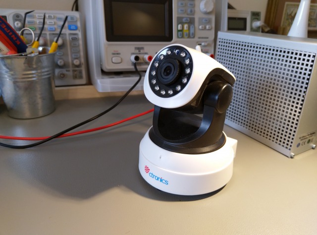
The device in question that we will be taking a look at, will be a smart, Linux-powered security camera. Before firing up the software, the correct serial port pins have to be located and measured. For this, an oscilloscope can be very helpful.
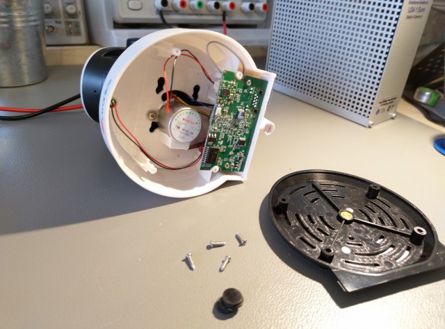
Taking the device apart is rather easy. There are just a bunch of screws located under the rubber feet of the camera. Opening up the device reveals a tiny motherboard that connects to the camera, motor and microphone through a few wires.
Examining the motherboard, a small, 4-pin connector in the top right stands out immediately.
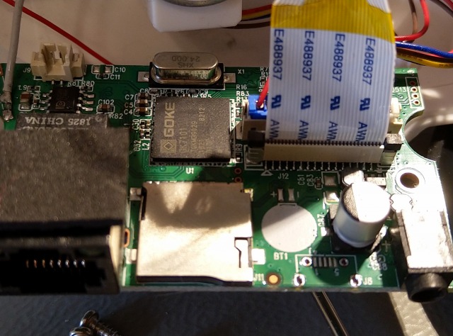
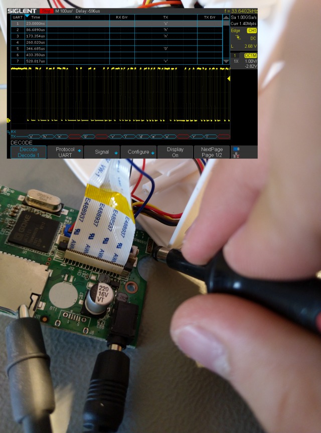
Usually, these UART headers have 3 to 5 pins with the following signals present: Ground, VCC (usually 3.3V), RX (Receive - to the device) and TX (Transmit - from the device). Often, there might be additional ground connections or other debug signals present. To determine the connector pinout, it makes sense to find the ground and power pins first. The ground can be determined in continuity mode to the metal shielding of components like micro SD card holders or USB connectors, while power usually reads a stable voltage that usually is 3.3V. Determining the transmit pin can most easily be done using a digital storage oscilloscope, which allows looking at the data signals. UARTs have a characteristic data frequency, as well as baud rate (usually 115200 baud) and idle state that defaults to a high logic level.
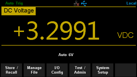
In this case, after determining the third pin from the top as ground, measuring between it and the first pin shows a stable 3.3V supply:
Connecting an oscilloscope and testing various, standard baud rates yields success on the last pin, as debug messages can be observed:
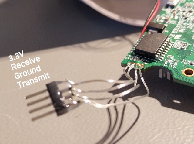
Next, we measure the remaining pin, which reads as 0V and does not change its state. We will assume that this is the receiving line. After determining the relevant pins, wires can be soldered to the identified locations and in turn, be soldered to a connector. Now, we have managed to identify and solder the following connections:
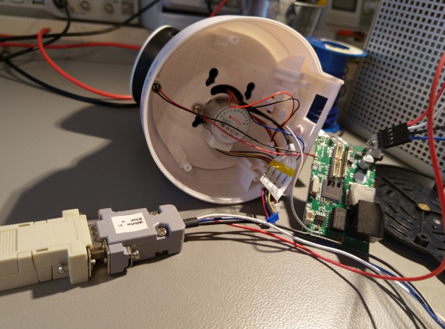
When using a USB serial converter, care must be taken to choose one that has the correct voltage levels (in this case 3.3V). The device under test or the converter will be damaged if either one of the devices uses a different voltage level than the other. My serial adapter automatically detects the correct voltage used via the exposed VCC pin on the debug connector.
At this point, the Serial Port Monitor can be started and a new session has to be opened by clicking the first icon in the toolbar. A window will be presented, that allows setting up various display parameters, as well as the serial port to use.
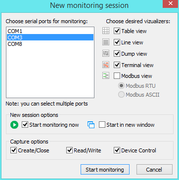
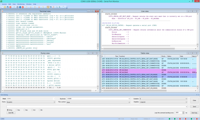
Selecting most of the available windows will yield an impressive view like this:
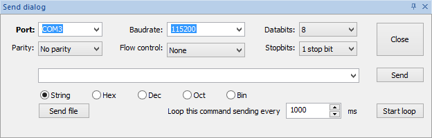
In this review, we want to connect to the camera with administrator access, so we look for ways to connect to a shell on the device. Sending decimal 13 after bootup will send a linebreak to the camera, which in turn displays a password prompt that will not accept any valid password. To finally log into the camera, one can use the bootloader - U-Boot in this case. Stopping autoboot and displaying a U-Boot prompt is simple, by sending decimal 13 right after inserting the power cord into the camera. Fortunately, the send dialog of the professional version of Serial Port Monitor helps us out here:
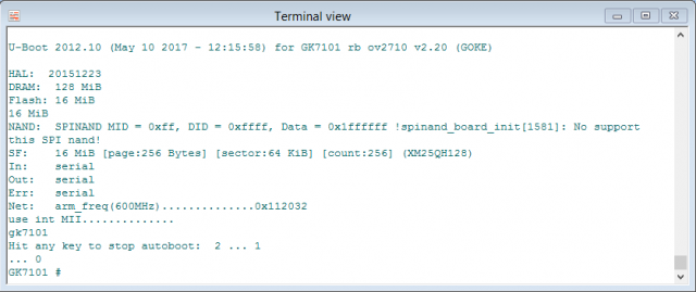
We will be greeted by a prompt like this:
The next step would be to print out the variables for U-Boot by sending printenv followed by decimal 13.
This will display the following list of variables - the highlighted one looks like a good candidate to be changed:
[PROCESS_SEPARATORS] printenv


arm_freq=0x00112032

baudrate=115200

bootcmd=run sfboot

bootdelay=2

bootfile=zImage

bsbsize=2M

consoledev=ttySGK0

ethact=gk7101

ethaddr=3C:97:0E:22:11:22

fileaddr=C1000000

filesize=200000

gatewayip=192.168.1.1

hostname="gk7101"

ipaddr=192.168.1.12

loadaddr=0xC1000000

mem=74M

netdev=eth0

netmask=255.255.255.0

nfsserver=11.1.4.19

phytype=0

rootfstype=rootfstype=jffs2 root=/dev/mtdblock3

rootpath=/opt/work

serverip=192.168.1.7

sfboot=setenv bootargs console=${consoledev},${baudrate} noinitrd mem=${mem} rw ${rootfstype} init=linuxrc ;sf probe 0 0;sf read ${loadaddr} ${sfkernel} ${filesize}; bootm

sfkernel=0x50000


soctype=0

stderr=serial

stdin=serial

stdout=serial

tftpboot=setenv bootargs root=/dev/nfs nfsroot=${nfsserver}:${rootpath},proto=tcp,nfsvers=3,nolock
ip=${ipaddr}:${serverip}:${gatewayip}:${netmask}:${hostname}:${netdev} mac=${ethaddr} phytype=${phytype} console=${consoledev},${baudrate} mem=${mem};tftpboot ${bootfile};bootm
Now, the variable has to be edited, but Serial Port Monitor does not directly support inputting VT100 keystrokes. This will demonstrate another interesting property of the professional version of Serial Port Monitor: being able to intercept connections already running. After closing the connection in the send panel of Serial Port Monitor, the connection can be re-opened in something like PuTTY which supports VT100:
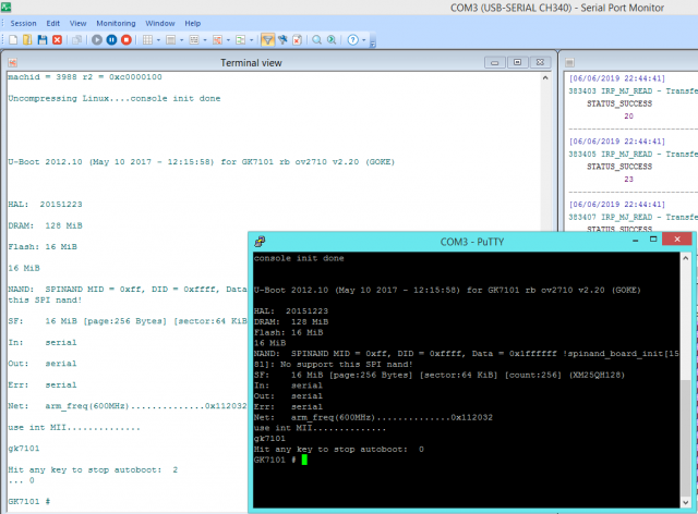
As we are still inside the bootloader, we can enter editenv sfboot and hit return to edit the boot command line. A good viewer might have already spotted that all communication to and from the camera done in PuTTY is visible in the Serial Port Monitor behind. Here in lies another quality of Serial Port Monitor that allows inspecting and monitoring a connection done through another program. The other program may not even have a command prompt but could be for instance an industrial control application that sends data to a CNC. In such a case, errors sent to the controller may be caught by observing the output afterwards.
Returning to the camera, we now cursor to the left in PuTTY until we reach the init=initrd part, which we change to init=/bin/sh to spawn a shell instead. Next, hit return and enter saveenv and reset both followed by hitting the return key.
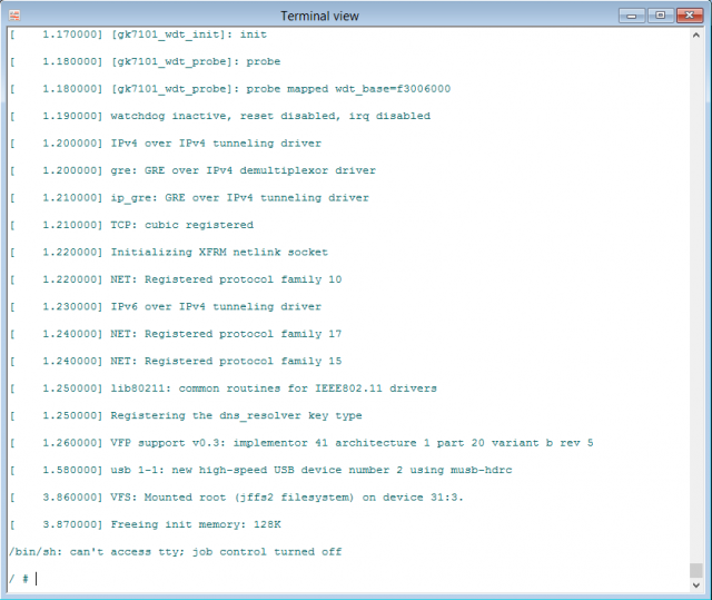
Now, the camera should reboot and indeed it does. We can now see the following screen, where the pound sign # indicates an active root shell.
Great! We have now established administrator access to our own camera.
To conclude, Eltima's Serial Port Monitor is a great product that works very well and is feature-packed. I would, personally, highly recommend it to anyone involved in embedded electronics. The user interface is well designed, the program is responsive, intuitive and feature-rich. The different views are all well executed and are useful for their specific tasks. Especially the timestamping and port intercepting are unique features that turn the Serial Port Monitor into the Wireshark of serial ports, which allows debugging most programs and protocols that use serial devices. The terminal colours can be changed via the settings. Desirable would be support for escape codes like \n in the send dialog. The size of the Serial Port Monitor is also a big plus, as it only takes up under 15 MB of disk space.
I did have some minor issues on one of my computers, where it refused to show the 'New session' dialog even after reinstalling, while on another one, the strict license checking kept it from working. I did, however, get it to work very well in the end and I am sure Eltima will be looking into the encountered issues.
Concerning serial ports, identifying them may be trivial on some boards but can be a challenge on others. Once they are identified, Serial Port Monitor easily displays the data that is being sent on the serial port and nicely reads it back along useful timing information that can be valuable for improving one's products by timing how long certain phases of the boot process take, even after the device has booted and using these metrics to determine areas that need improvement. This is an invaluable benchmark for embedded systems designers like me and I will surely be using it for that in future projects. Serial Port Monitor can be purchased in full or downloaded free of charge at https://www.com-port-monitoring.com/.